Staging & Setup
A minimum ceiling height of 8ft is required.
1.) Identify the areas within the room where the stands will be placed.
It is very important that the stands are facing each other and can be aligned precisely.
2.) Mark the area where the stands will be placed.
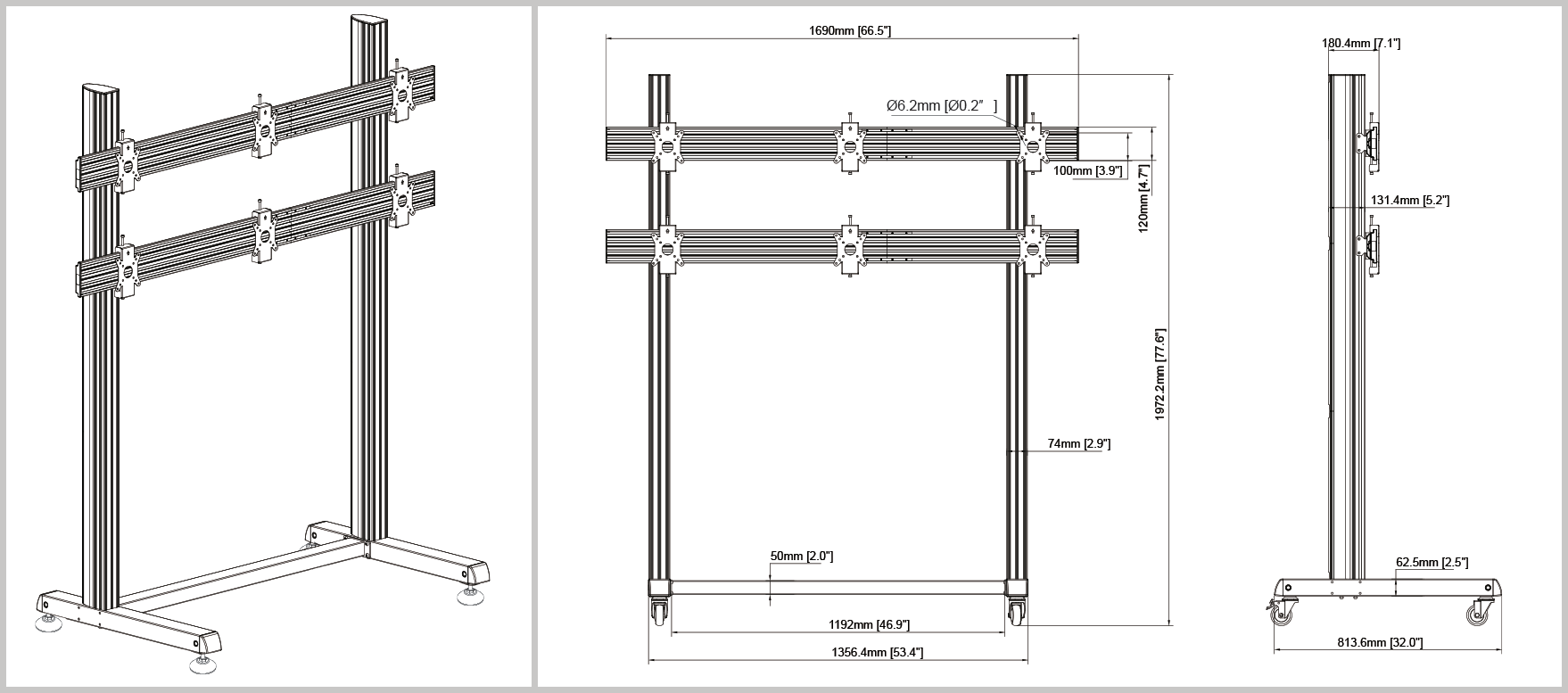
- Area Needed (Per Stand):
- Journey Stand: 82.5″ wide x 36″ long
- Dream Stand: 82.5″ wide x 44″ long
- Awakening Stand: 98″ wide x 44″ long

PRO Tips:
Clear at least 4ft x 8ft of space to build your stands
Organize your boxes before installation
“Pro Tips” callouts (e.g. “Lay down padding to avoid scratches.”)
Required Tools (Not Included):
Power Drill with 6″ extended bit.
Hex Key Drill Bits: (3mm, 5mm & 6mm)
Self Leveling Alignment Laser (Suggested: BOSCH GPL100-50G)
Laser Distance Measure (Suggested: BOSCH GLM165-40 Blaze)
- Torpedo Level
Team Needed:
Minimum of 2
Skill level (Experienced Audio/Visual Equipment Installer)
Estimated setup time: 3-5 hours per stand.
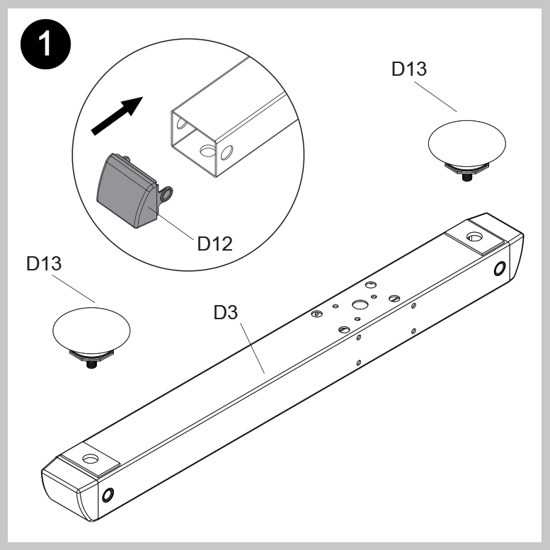
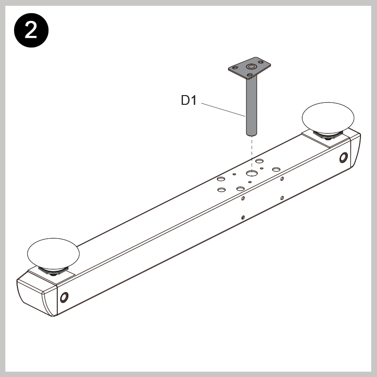
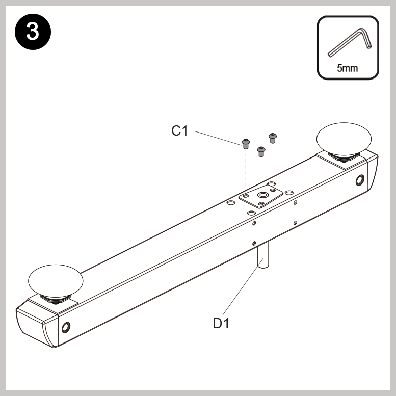
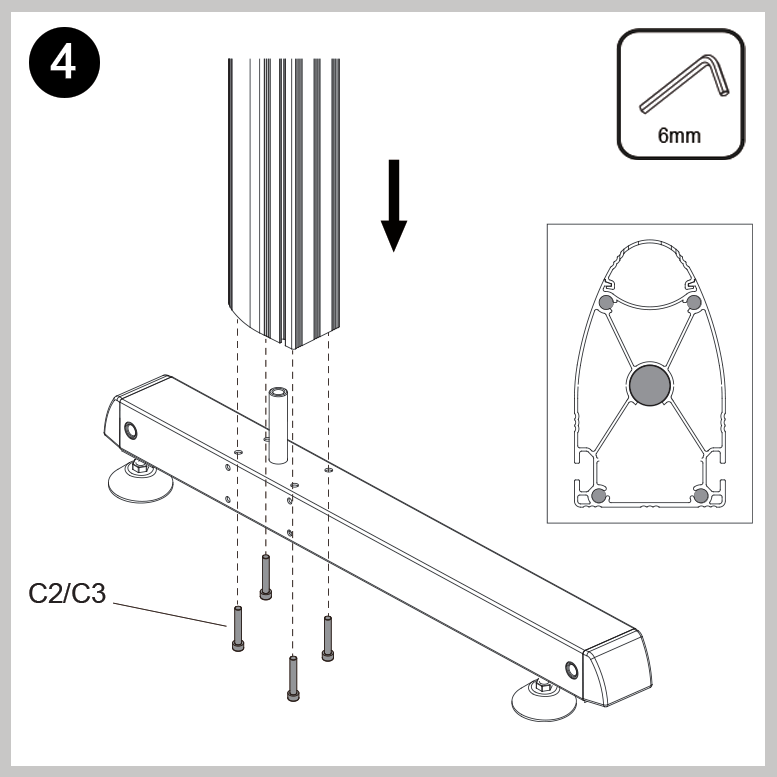
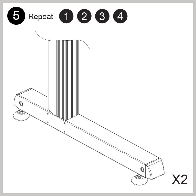
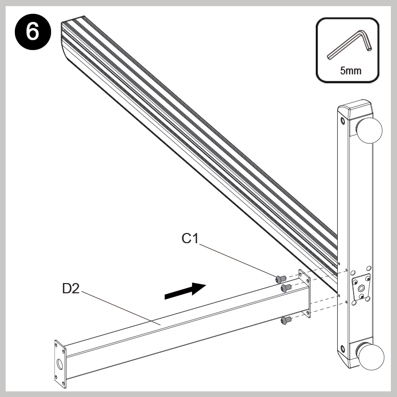
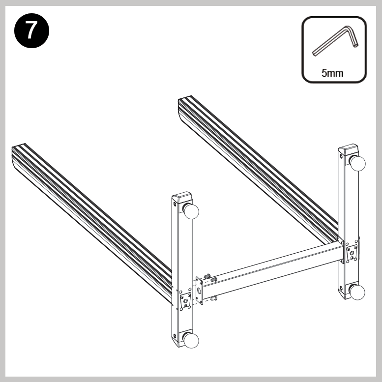
Step 2: Assemble the Stands
Below is a step-by-step visual guide on how to properly assemble each stand
The stand should be built on its back with the top elevated to a small angle by using a box underneath

Journey Stand Assembly
6-screen stand
- Locate stand boxes
Parts List

Installation
Step 3: Mount the Monitors
Unbox monitors and set aside the HDMI cords and Power Cables.
Remove all stickers and packaging.
Disregard the included monitor stands.
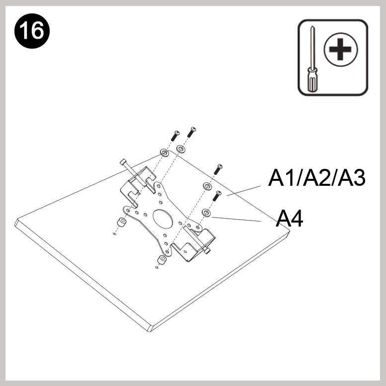
Locate all 12 Monitor Mounts (D8) and Fasteners (A1).
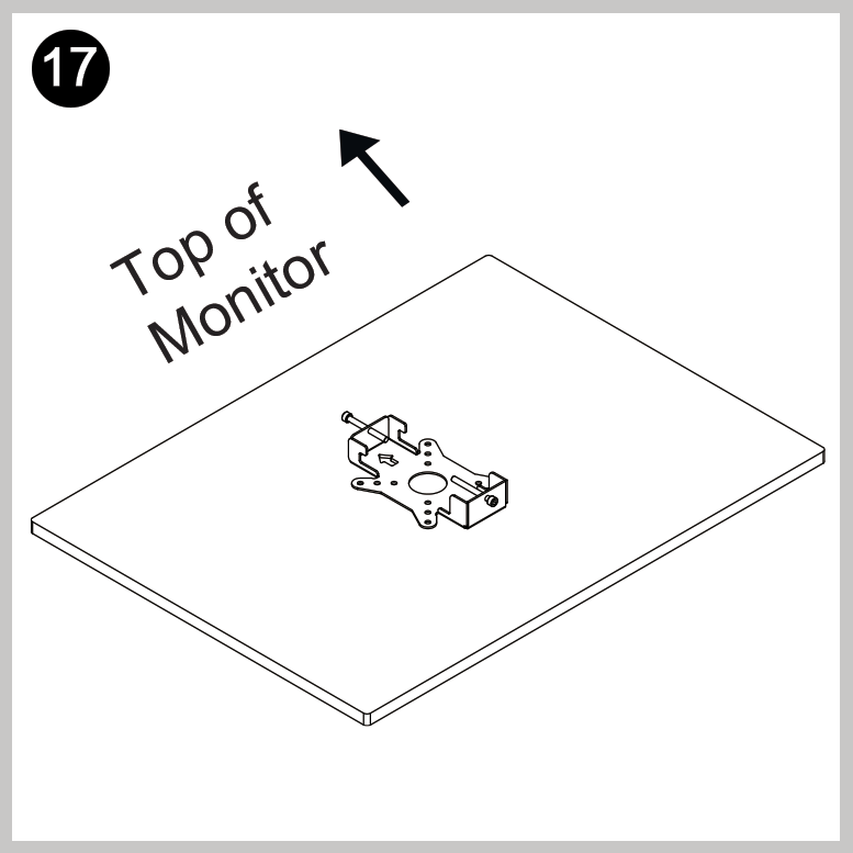
- Affix the mounts to each monitor, ensuring the arrow on the mounts are facing the top of each monitor.
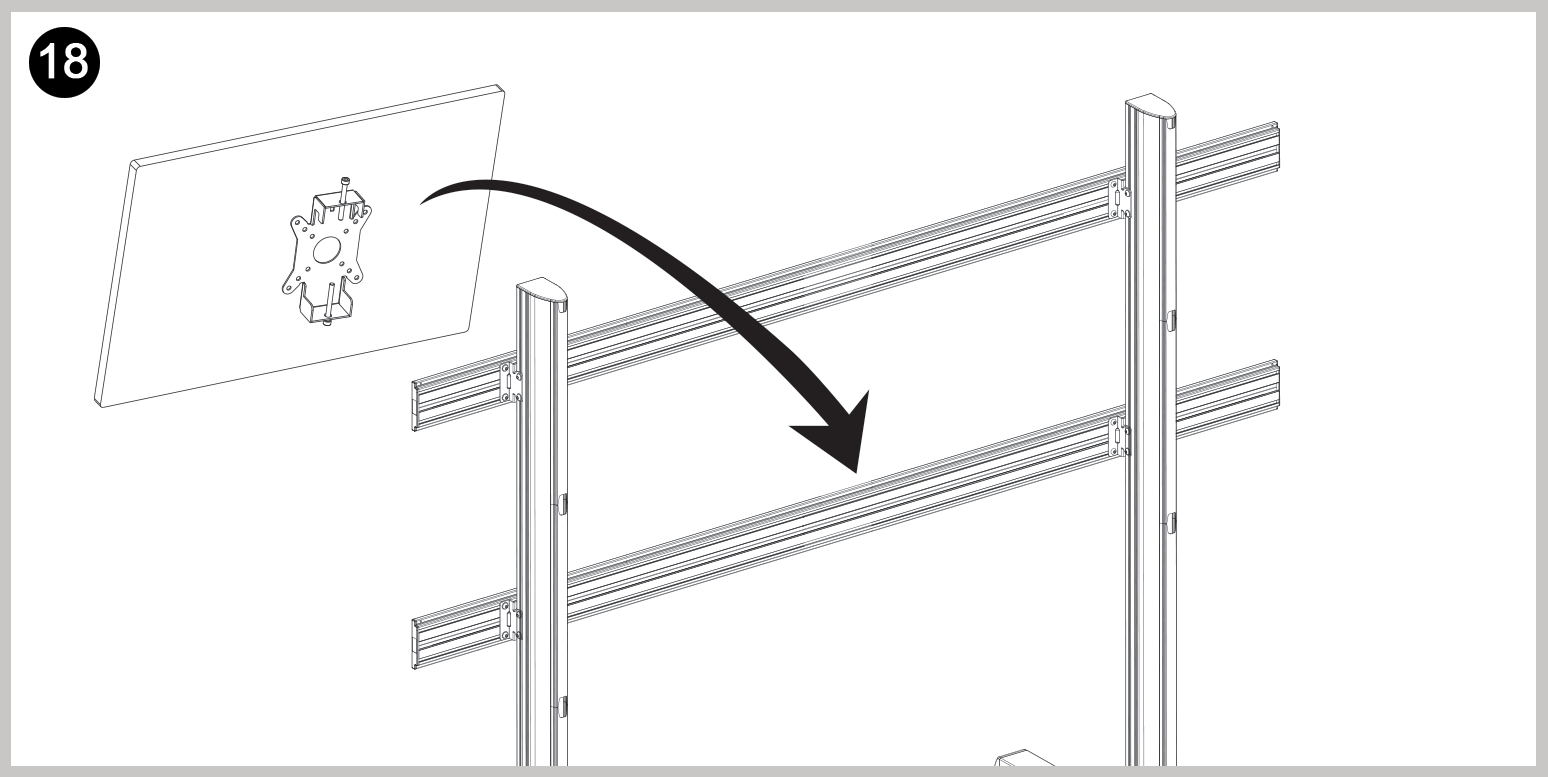
- Mount the center monitor(s) on the bottom row, then add monitors to each side.
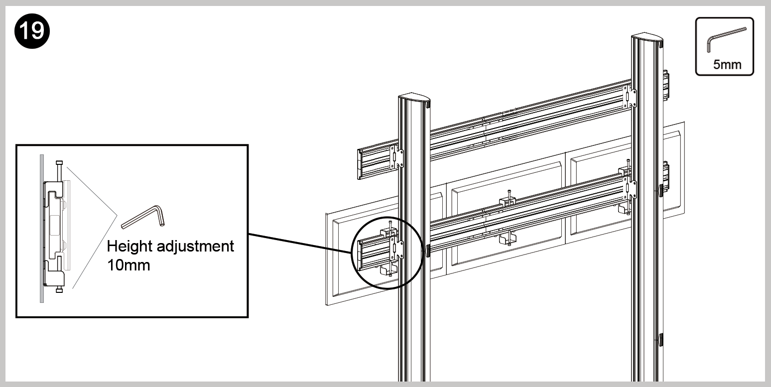
- Adjust monitor height using mount screws
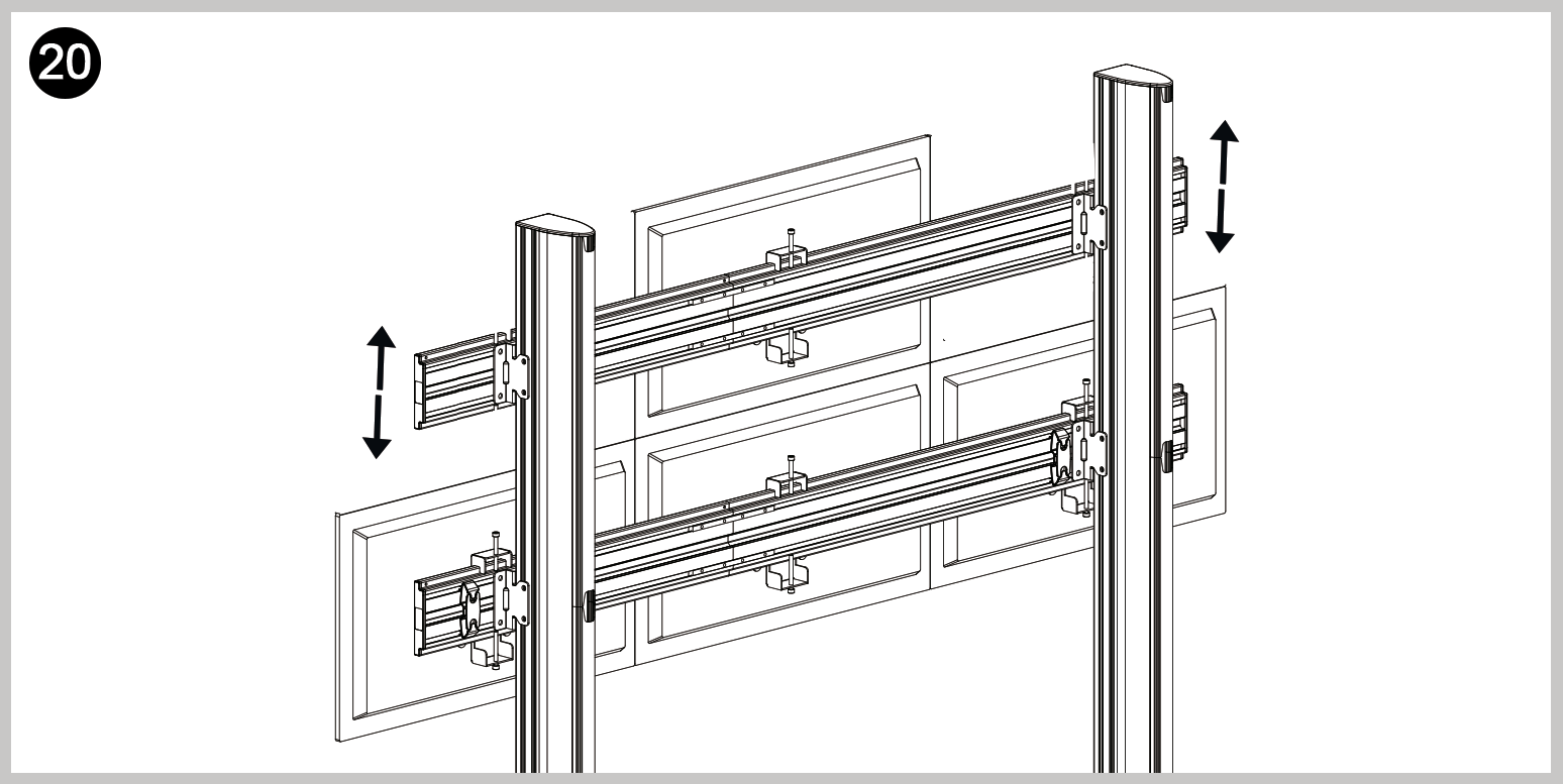
- Finish mounting all monitors on the bottom row and start on the next row up, beginning in the center.
- Adjust the height of the next bar up as needed to ensure the monitors are flush mounted.
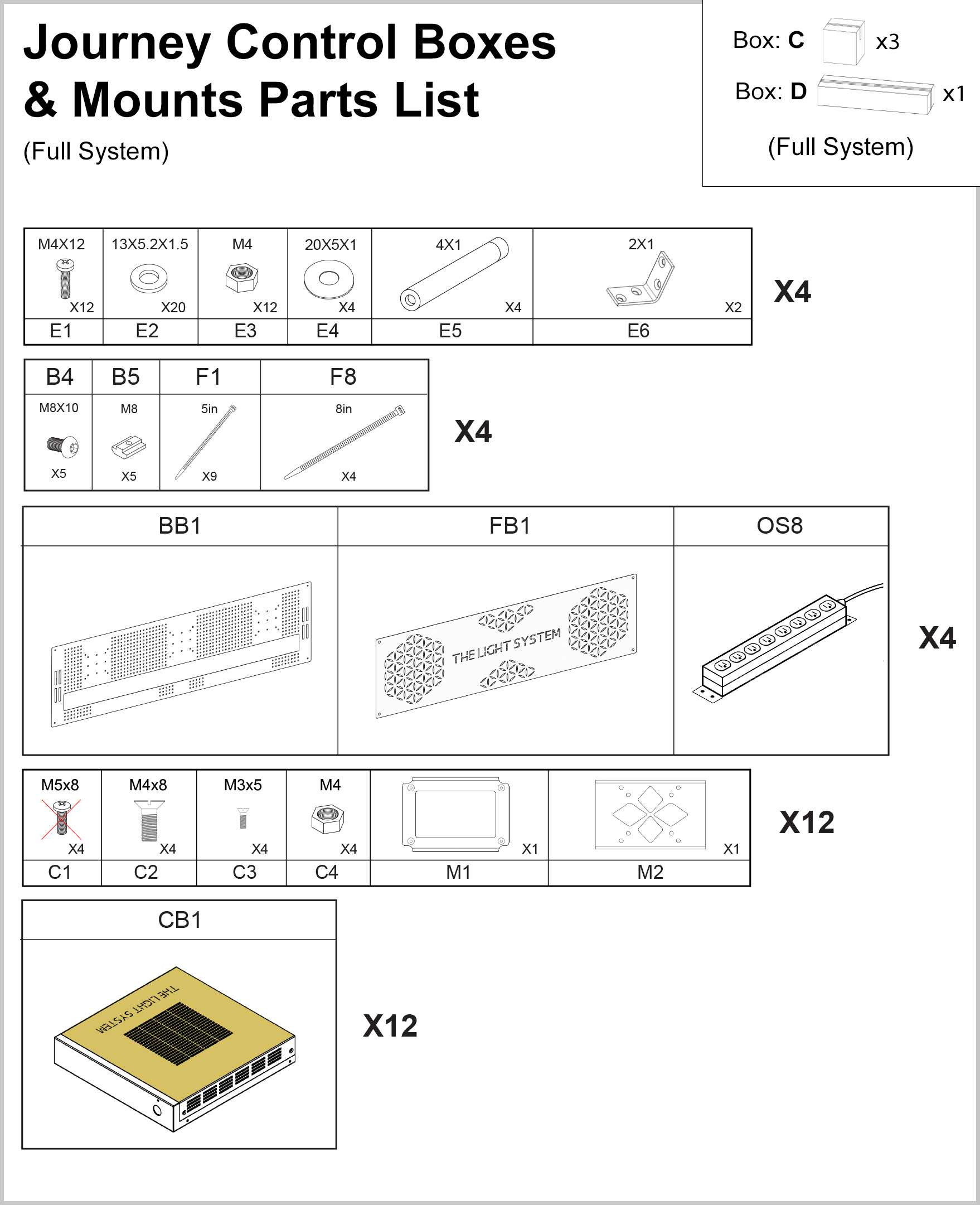
Journey Mount Board Assembly
Parts List
Installation
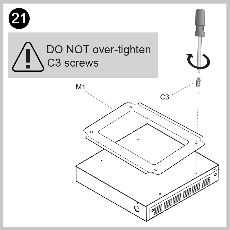
- Install the M1 mount backs to each Control Box (CB1). Do Not over-tighten screws.
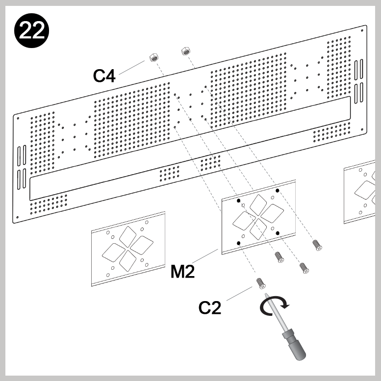
- Install the M2 mount backs onto the backboards.
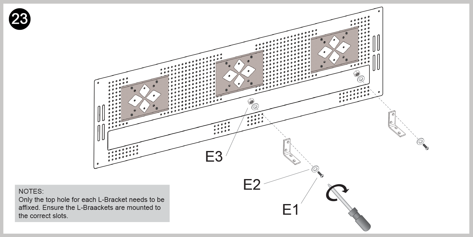
- Install L-brackets to the backboard.

- Affix outlet strip to L-brackets.
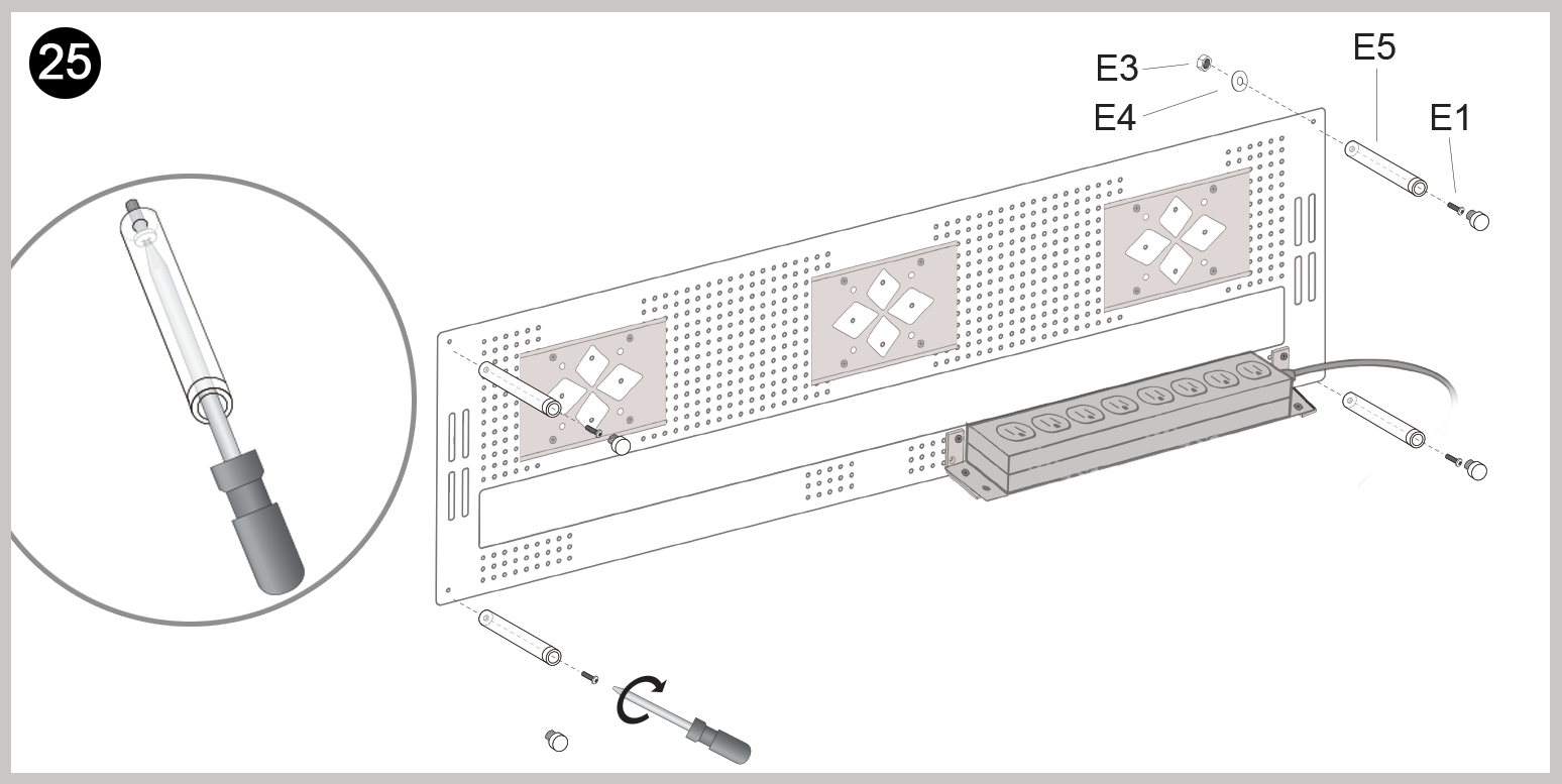
- Install stand-off screws.
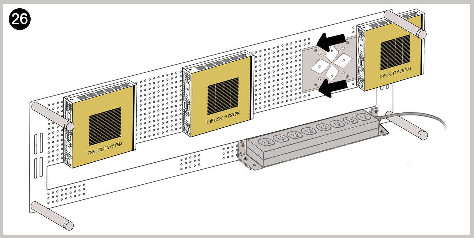
- Slide control boxes (with mounts installed) onto the backboard mounts. Make sure they are attached correctly.
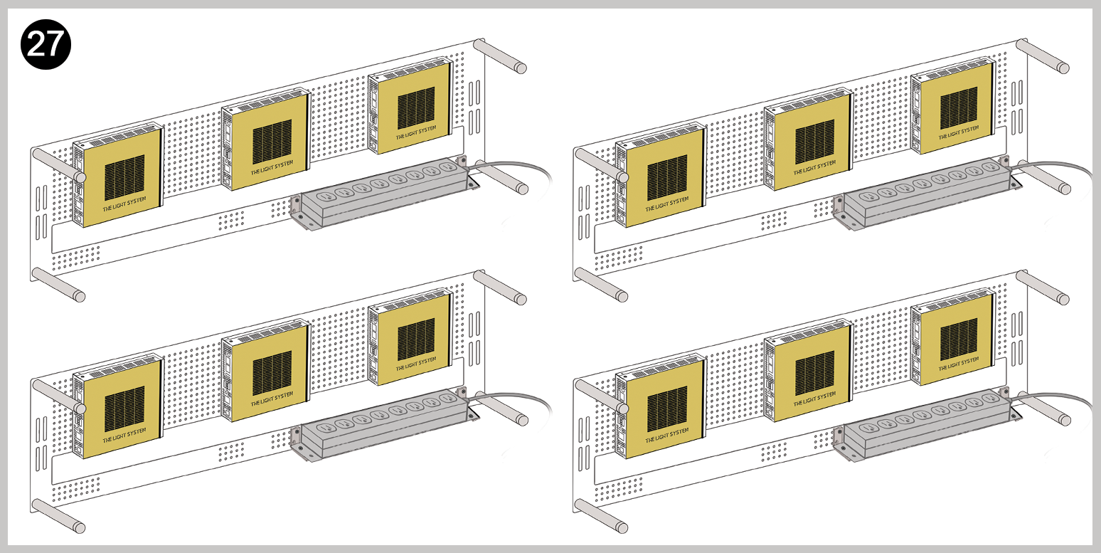
- After Step 26 is complete, repeat Steps 22-26 for the 3 remaining backboards.
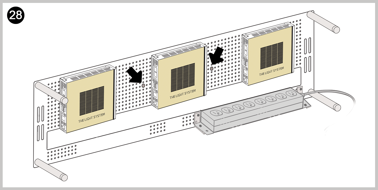
- Locate pilot holes. These holes (2) will be close to the middle of the board and will be slightly larger than the other holes.
- The pilot hole will be were the first screw attaches the backboard to the stand. This will guide the placement of the backboard on the crossbar, while anchoring the backboard into place for easier mounting.
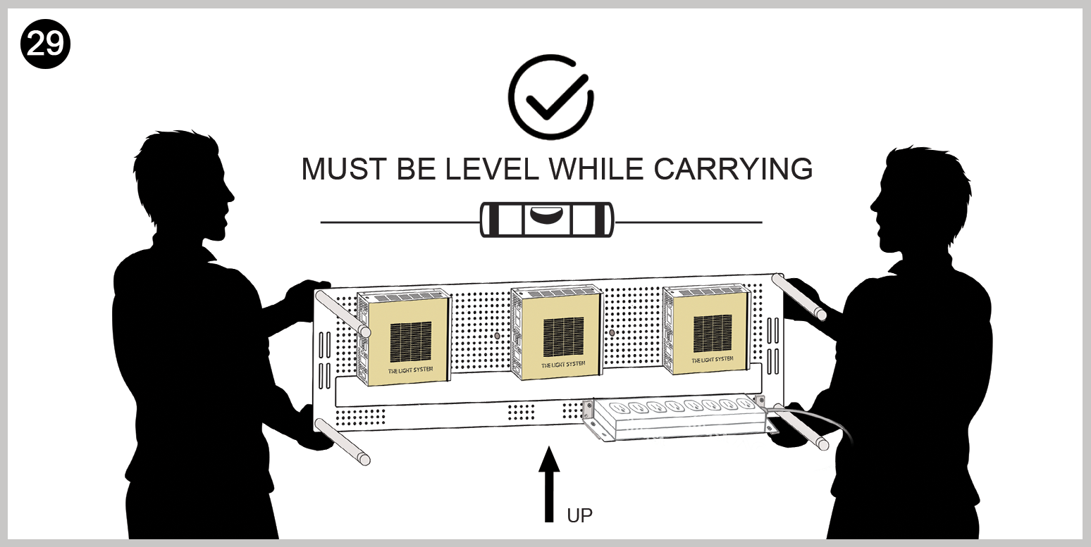
- Lift the completed mount board using two people.
- *** To prevent Control Boxes from sliding off while carrying: Ensure the mount board is vertical and level while carrying it to the stand for mounting.
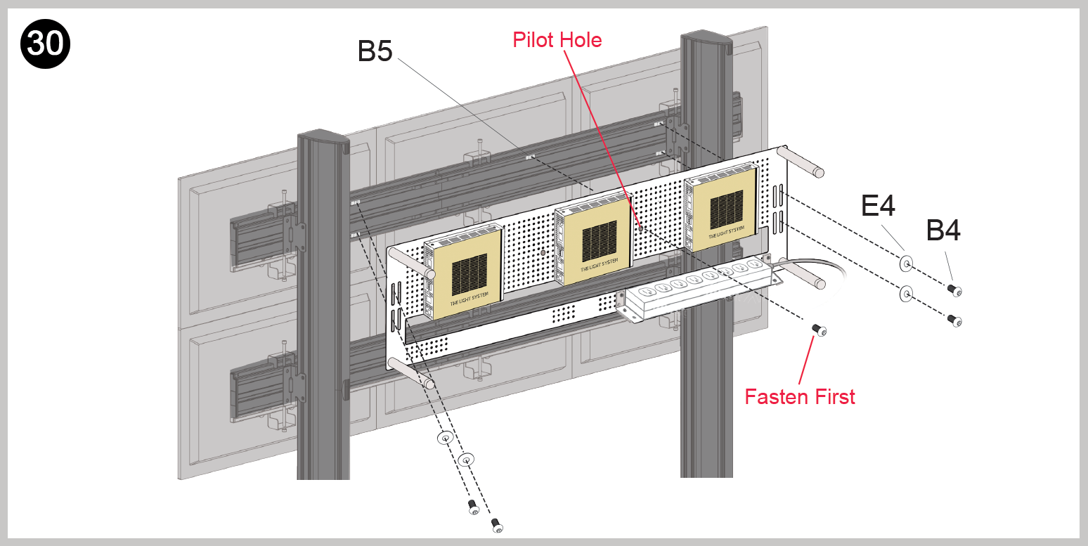
- Affix the backboard to the top row of the stand by fastening the B4 screw to the B5 slide nut, through the Pilot Hole. (Mounting backboards, beginning with the top row, will make installation easier.
- Once the first B4 is affixed, screw the remaining (x4) B4 nuts with E4 washers to the B5 slide nuts.
- ****Note: 3 people are required to install each backboard. Two at either side and one person to screw in the fasteners. Holes on the backboard need to be aligned with the B5 slide nuts.
- Once the backboard is successfully fastened to the top crossbar, begin wiring before subsequent backboards are installed.
Step 5: Wiring
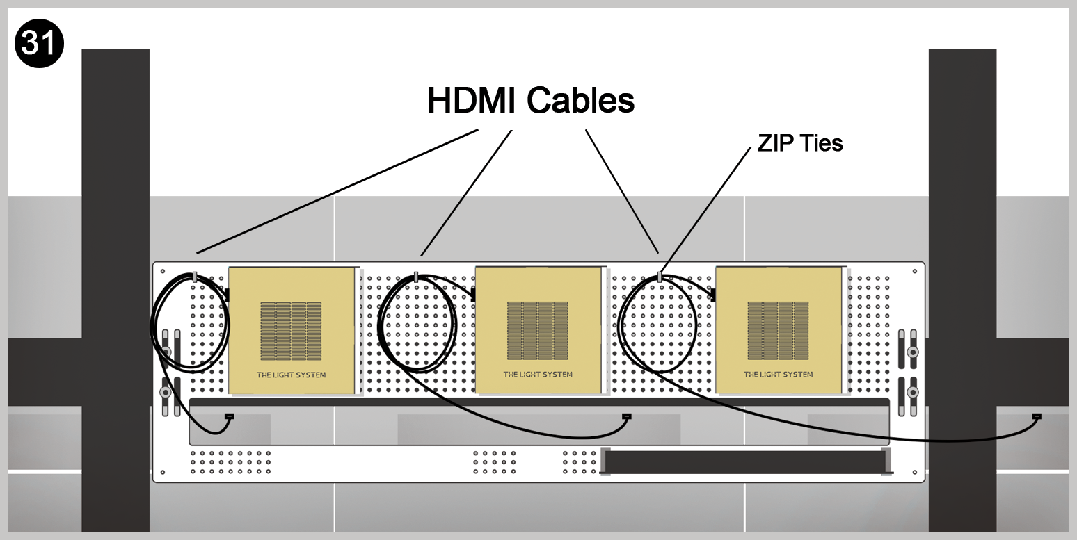
- Begin by connecting the HDMI cables to the monitors, then the Control Box.
- Each HDMI cord can be coiled and affixed to the backboard by provided Zip Ties.
- ****Note: Do not coil the HDMI cords too tight or bend them in sharp angles, as that may damage the connection.
- ****Note: Each backboard should be wired as they are mounted. This will make ports on the monitors easier to access.
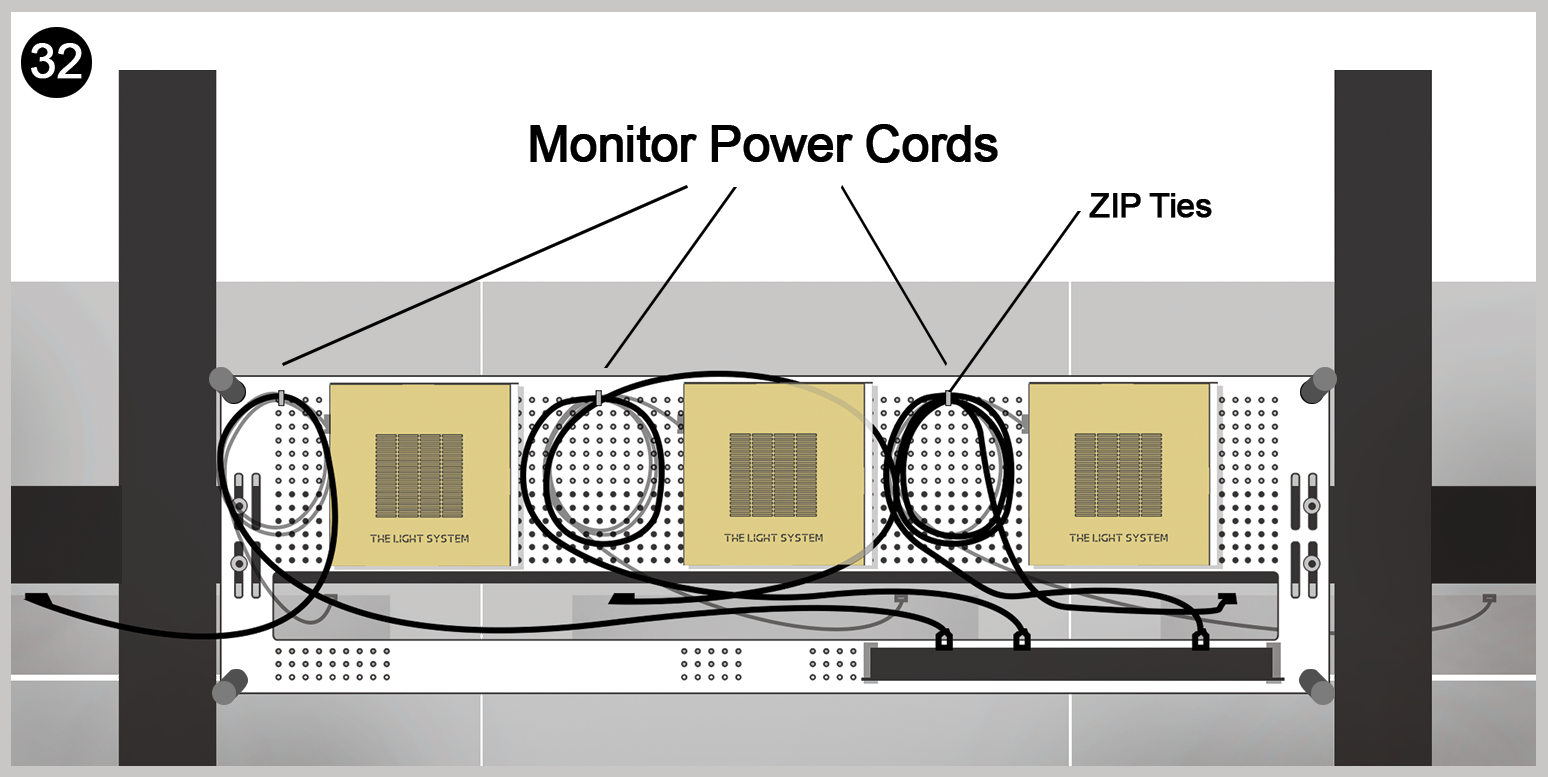
- Connect the Monitor power cords to the outlets on the power strip.
- Coil the power cords in a similar pattern as the HDMI cables and attach to the backboard with Zip Ties.
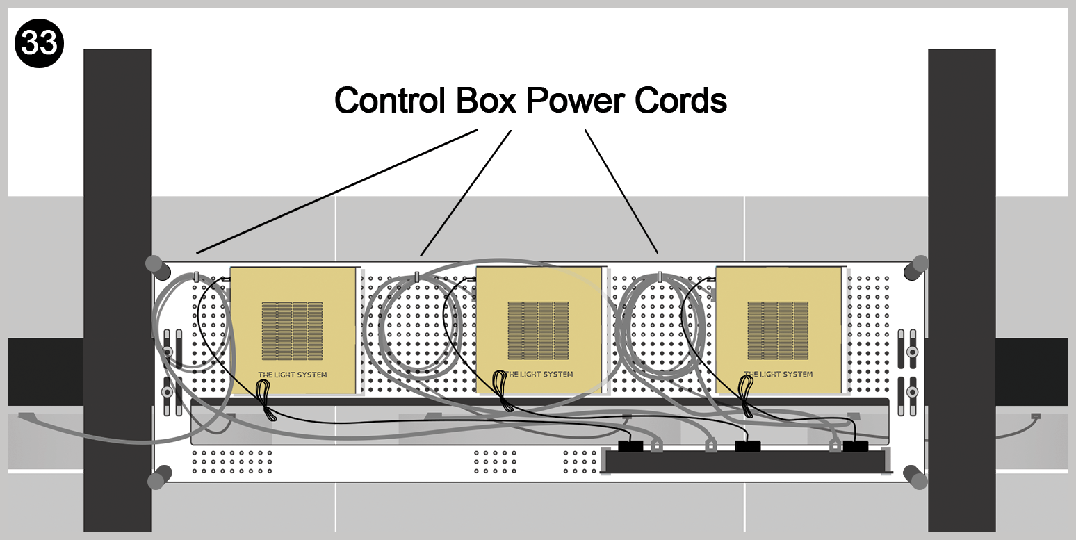
- Connect the Control Box power cords to the outlets on the power strip.
- Ensure the power box is plugged into the outlet strip with bottom facing toward the monitors.

- Repeat steps 28 – 33 for each backboard, mounting rows from top to bottom.
- Thread outlet strip power cord into stand pole slots.
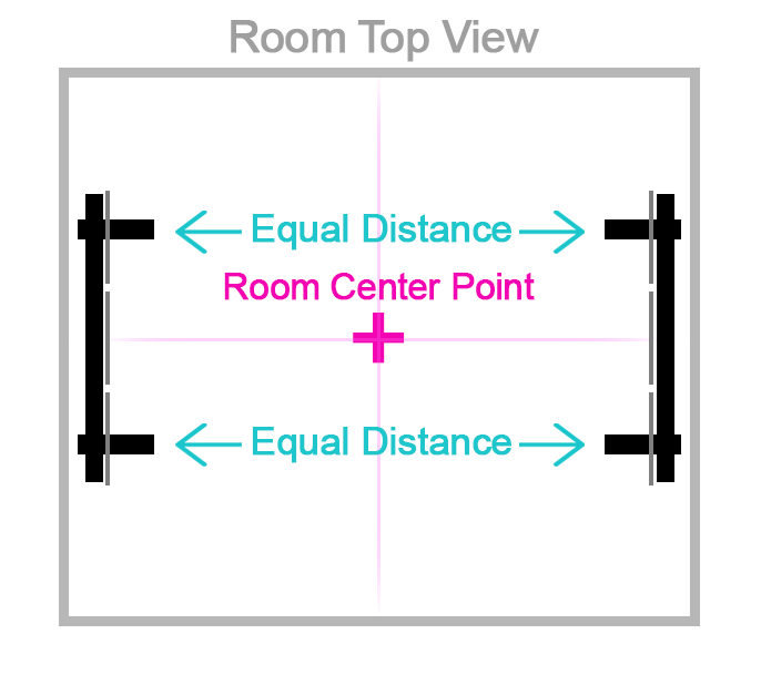
Step 6: Alignment

- Ensure both stands are completely level by adjusting the height of the stand feet (D13)
- Ensure crossbar heights on both stands are at identical heights.

- Position the stands facing one another at equal distance from the room’s center point

- Align the feet of the opposing stands with a laser guide.

- Measure and adjust the distance between each stand foot that face one another.
- Ensure the distance between both sets of stand feet are identical.
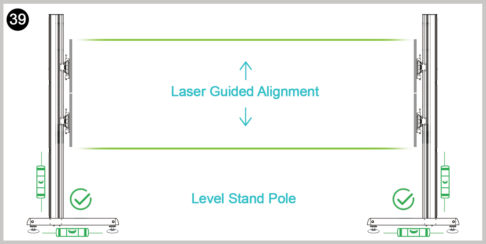
- Ensure stand poles are level on each stand.
- Alignment of stand poles can be achieved by adjusting stand feet (D13).
- Check monitor alignment with Laser Alignment Device.
Step 7: Programming the System
Initial Setup

Connect the keyboard to each control box and begin programming one by one.
Access the Programming Guide Here

- Once all control boxes have been programed, begin mounting the Front boards using the Stand-off Screws (E5).